Networks are the most critical component of an effective enterprise IT environment.
Network services from I0T Inc. support your network’s growing need for agility, security and scalability in a multi-vendor, multi-technology environment. We provide straightforward guidance and extensive knowledge on networking across industries, and we use a lifecycle approach that spans strategy, assessment, planning, design, implementation and management. Our services range from network connectivity consulting and integration to managed network services and software-defined networking.
We have been tasked with designing and implementing VPN infrastructure to connect six offices located around the world.
The solution should includes inter-site connectivity and remote access. It should include the following:
I0T Inc. Networking Team applies the KISS principle wherever possible while balancing the needs of our organization.
The solution proposes to deploy a site-to-site VPN on IP Security (IPSec) tunneling over Internet between the six remote sites and to provide a secure PPTP / L2TP service for remote users’ (Dial in VPN users) over Internet
The solution design is based on the vendor best practices to build a site-to-site enterprise virtual private network (VPN). The proposed solution is using Mikrotik VPN router products.
The reason these technologies are selected is I wanted to keep the solution simple and straight forward while at
the same time meeting of most organization’s need.
This document describes the proposed solution topology diagram, IP addressing scheme, the individual hardware requirements and their interconnections, software features, transport mediums, security and reliability.
CONFEDINTIALITY
This document is made for the subject exercise for I0T’s Do It Yourself.
Topology diagram and IP addressing scheme
The IPSec standard provides a method to manage authentication and data protection between multiple peers engaging in secure data transfer.
IPsec protocol suite can be divided in following groups:
This solution requires a standards-based way to secure data from eavesdropping and modification. IPSec provides such a method. IPSec has a choice of transform sets so that users may choose the strength of their data protection. IPSec also has several hash methods to choose from, each giving different levels of protection.
Each site will need to establish a peer IPSec tunnel with all the other sites. Will need 5 tunnels for each each site, see the below diagram.
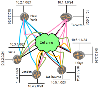
Diagram # 1 – IPSec Tunnels
The following hardware and software will be required for the setup:
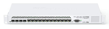
Gateway Router: Two redundant (active-standby) Mikrotik router of the following model running latest RouterOS will be required in each site. Mikrotik CCR1036-12G-4S Router: 1U rackmount, 12x Gigabit Ethernet, 4xSFP cages, LCD, 36 cores x 1.2GHz CPU, 4GB RAM, 24 mppsfastpath, Up to 16Gbit/s throughput, RouterOS L6
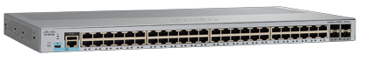
LAN Switch: Two redundant (active-active) Cisco Catalyst 2960-L with 48 ports: Fixed or Smart Managed, LAN Lite, Data or PoE+, Up to 370W PoE, 4 SFP or SFP+ uplinks Enhanced Limited Lifetime Warranty (E-LLW)

Reliable Internet Link preferred with backup and SLA: Symmetrical or Asymmetrical high speed Internet connection with FIXED IP ADDRESS, speed based on forecasted traffic, recommendation is 100 – 500Mbps download/upload speed. Type of connections is based on availability, and can be in preference:
a. Fiber
b. Copper
c. Wireless P2P (reliable)
Link backup and redundancy can be provided based on availability. Solutions like, SD-WAN, 2G/3G/4G/LTE or 5G that can combine different link types and provide bonding on a single channel to provide the largest possible amount of bandwidth.
Site Network Diagram and configuration
The Internet router will provide an Ethernet connection to the Mikrotik gateway router and a Fixed IP address. The below diagram is for Toronto site, however, all other sites will have similar setup.
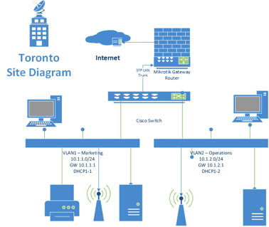
LAN setup
/system identity set name=Toronto
/interface vlan> add name=VLAN1 vlan-id=1 interface=sfp1 disabled=no
/interface vlan> add name=VLAN2 vlan-id=2 interface=sfp1 disabled=no
/ip address> add address=10.1.1.1/24 interface=VLAN1
/ip address> add address=10.1.2.1/24 interface=VLAN2
WAN Setup
/ip address=1.1.1.1/24 interface=ether1
/ip route add gateway=1.1.1.2/24
/ip dnsset servers=8.8.8.8
/ip firewall nat add action=masquerade chain=srcnat out-interface=ether1
We will limit the configuration to only one site (Toronto), as other sites will have a similar configuration but with different IP addressing.
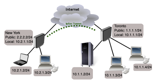
Start off by configuring IPsec peer. It is enough to configure address, auth method and secret parameters and leaving everything else as default. However, it is possible to set additional Peer properties as long as they are identical between both sites.
/ip ipsec peer
add address=2.2.2.2/32
auth-method=pre-shared-key secret=”T0r0nt0$123!#$”
For the next steps, it is important that proposed authentication and encryption algorithms match on both routers. we will use predefined “default” proposal. To verify Proposal settings:
[admin@MikroTik] /ip ipsec proposal print
Flags: X - disabled, * - default
0 * name="default" auth-algorithms=sha1
enc-algorithms=aes-256-cbc,aes-192-cbc,aes-128-cbc lifetime=30m
pfs-group=modp1024
/ip ipsec policy
add src-address=10.1.1.0/24 src-port=any dst-address=10.2.1.0/24 dst-port=any \
sa-src-address=1.1.1.1/32 sa-dst-address=2.2.2.2/32 \
tunnel=yes action=encrypt proposal=default
At this point if you try to send traffic over the IPsec tunnel, it will not work, packets will be lost. This is because both routers have NAT rules (masquerade) that is changing source address before packet is encrypted. Router is unable to encrypt the packet, because source address do not match address specified in policy configuration.
To fix this we need to set up NAT bypass rule.
/ip firewall nat
add chain=srcnat action=accept place-before=0 \
src-address=10.1.1.0/24 dst-address=10.2.1.0/24
It is very important that bypass rule is placed at the top of all other NAT rules.
Another issue is if you have Fasttrack enabled, packet bypasses IPsec policies. So we need to add accept rule before Fasttrack, However this can add significant load to CPU if there is a fair amount of tunnels and significant traffic on each tunnel. Solution is to use RAW firewall tables to
bypass connection tracking, that way eliminating need of filter rules listed above and reducing load on CPU by approximately 30%.
/ip firewall filter
add chain=forward action=accept place-before=1
src-address=10.1.1.0/24 dst-address=10.2.1.0/24 connection-state=established,related
add chain=forward action=accept place-before=1
src-address=10.1.1.0/24 dst-address=10.2.1.0/24 connection-state=established,related
/ip firewall raw
add action=notrack chain=prerouting src-address=10.1.1.0/24 dst-address=10.2.1.0/24
add action=notrack chain=prerouting src-address=10.1.1.0/24 dst-address=10.2.1.0/24
MikroTik routers requires password configuration, we suggest to use pwgen or other password generator tool to create secure and non-repeating passwords,
/user set 0 password="!={Ba3N!"40T_X+GvKBz?jTLIUcx/,"
Besides the fact that default firewall protects your router from unauthorized access from outer networks, it is possible to restrict username access for the specific IP address
/user set 0 allowed-address=x.x.x.x/yy
/ip ssh set strong-crypto=yes
All production routers must be administered by SSH, secured Winbox or HTTPs services. Use the latest Winbox version for secure access. Note, that in newest Winbox versions, “Secure mode” is ON by default, and can’t be turned off anymore.
/ip service disable telnet,ftp,www
and also, change the default port, this will immediately stop most of the random SSH bruteforce login attempts, disable mac-telnet services, Disable mac-winbox services, Disable mac-ping service, disable MikroTik Neighbor discovery protocol, disable Bandwidth server, disable DNS cache, disable proxy and socks, UPNP service, dynamic name service, disable lcd
/ip service set ssh port=2200
/tool mac-server set allowed-interface-list=none
/tool mac-server mac-winbox set allowed-interface-list=none
/tool mac-server ping set enabled=no
/ip neighbor discovery-settings set discover-interface-list=none
/tool bandwidth-server set enabled=no
/ip dns set allow-remote-requests=no
/ip proxy set enabled=no
/ip socks set enabled=no
/ip upnp set enabled=no
/ip cloud set ddns-enabled=no update-time=no
/lcd set enabled=no
We strongly suggest to keep default firewall on. Here are few adjustments to make it more secure:
work with new connections to decrease load on a router; create address-list for IP addresses, that are allowed to access your router; enable ICMP access (optionally); drop everything else, log=yes might be added to log packets that hit the specific rule;
/ip firewall filter
add action=accept chain=input comment="default configuration" connection-state=established,related
add action=accept chain=input src-address-list=allowed_to_router
add action=accept chain=input protocol=icmp
add action=drop chain=input
/ip firewall address-list
add address=1.1.1.1, 2.2.2.2,3.3.3.3,4.4.4.4,5.5.5.5 list=allowed_to_router
Remote users can connect a computer to a remote office network over a PPTP encrypted tunnel giving that computer an IP address from the same network that the remote office has (without any need of bridging over EoIP tunnels).
PPTP is a secure tunnel for transporting IP traffic using PPP. PPTP encapsulates PPP in virtual lines that run over IP. PPTP incorporates PPP
and MPPE (Microsoft Point to Point Encryption) to make encrypted links. The purpose of this protocol is to make well-managed secure connections between routers as well as between routers and PPTP clients (clients are available for and/or included in almost all OSs including Windows). Multilink PPP (MP) is supported in order to provide MRRU (the ability to transmit full-sized 1500 and larger packets) and bridging over PPP links (using Bridge Control Protocol (BCP) that allows the sending of raw Ethernet frames over PPP links). This way it is possible to setup bridging without EoIP. The bridge should either have an administratively set MAC address or an Ethernet-like interface in it, as PPP links do not have MAC addresses. PPTP includes PPP authentication and accounting for each PPTP connection. Full authentication and accounting of each connection may be done through a RADIUS client or locally.
MPPE 128bit RC4 encryption is supported.
PPTP traffic uses TCP port 1723 and IP protocol GRE (Generic Routing Encapsulation, IP protocol ID 47), as assigned by the Internet Assigned Numbers Authority (IANA). PPTP can be used with most firewalls and routers by enabling traffic destined for TCP port 1723 and protocol 47 traffic to be routed through the firewall or router.
PPTP connections may be limited or impossible to setup though a masqueraded/NAT IP connection. Please see the Microsoft and RFC links listed below for more information.
/interface pptp-server server set enabled=yes
/ip firewall filter
add action=accept chain=input comment="PPTP” protocol=gre
add action=accept chain=input comment=”PPTP protocol=tcp dst-port=1723
Office router (Toroto mikrotik for example) is connected to internet through ether1. Workstations are connected to spf1 via a Cisco switch on VLAN1 and VLAN2.
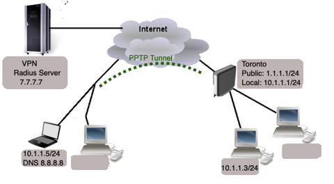
Remote users can connect a computer to a remote office network over a PPTP encrypted tunnel giving that computer. RADIUS, short for Remote Authentication Dial-In User Service, is a remote server that provides authentication and accounting facilities to various network appliances. RADIUS authentication and accounting gives the ISP or network administrator ability to manage PPP user access and accounting from one server throughout a large network. The MikroTik RouterOS has a RADIUS client which can authenticate for HotSpot, PPP, PPPoE, PPTP, L2TP and ISDN connections. The attributes received from RADIUS server override the ones set in the default profile, but if some parameters are not received they are taken from the respective default profile. The RADIUS server database is consulted only if no matching user access record is found in router’s local database.
Traffic is accounted locally with MikroTik Traffic Flow and Cisco IP pairs and snapshot image can be gathered using Syslog utilities. If RADIUS accounting is enabled, accounting information is also sent to the RADIUS server default for that service.
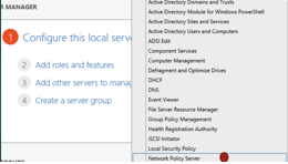
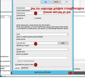
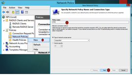
Install and register the Radius server along with Network policy. This will be out of this exercise scope. But here some screen shots on how to configure it. Radius will use a database for portal use also.
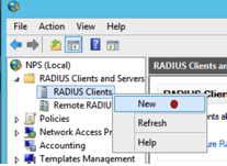
Now configure the Mikrotik to forward ppp AAA requests to the RADIUS server.
/radius add service=hotspot,ppp address=7.7.7.7 secret=”I0TSecret”
/ip firewall filter add chain=input protocol=udp port=1701, 500, 4500 add chain input protocol=ipsec-esp
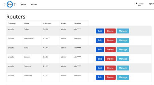
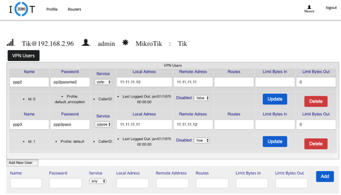
The Mikrotiks and the VPN users’ management can be handled by a web platform I created for that reason and can be accessed via https://tik.i0t.ca.
MikroTik routers configuration will be backup every month and upon changes. The following script will be configured on each router. Will limit to Toronto in this exercise. Additionally, one backup system will be ready for replacement in each site in the case of hardware failure.
dd dont-require-permissions=no name=Backup owner=admin policy=\
ftp,read,policy,test,sensitive source=":log info \"Starting backup\";\r\
\n/system backup save name=\"MK\"\r\
\n:delay 00:00:11\r\
\n/tool e-mail send file=\"MK.backup\" to=\"[email protected]\" body=\"Mikrotik\
\_Router BACKUP File Attached.\" \\\r\
\n subject=\"MK BACKUP FILE \$[/system clock get date] at \$[/system cl\
ock get time] Script\"\r\
\n:delay 00:00:01\r\
\n/export file=\"MK\"\r\
\n:delay 00:00:10\r\
\n/tool e-mail send file=\"MK.rsc\" to=\"[email protected]\" body=\"Mikrotik Ro\
uter Backup SCRIPT File Attached.\" \\\r\
\n subject=\"BACKUP SCRIPT FILE \$[/system clock get date] at \$[/syste\
m clock get time] Script\"\r\
\n:log info \"Backup script completed\"\r\
\n"
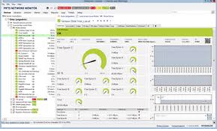
PRTG will be used as the monitoring and alerting system. SNMP Ver. 3.0 will be configuration in the router to monitor the Bandwidth,
interfaces status, logged in users,
In order to manage the use of the Internet bandwidth available for each site, a queuing policy will be applied. A shaper will be installed, who are limited at 50 Mbit/s of overall Bandwidth, what includes around 100 users online with different rates limited 1 Mbit/s and 2 Mbit/s per user. The idea behind the scripts is for allowing different limits Day and Night, to give to the lowest priority to reach at least 22 Mbit/s after businesses hours, when business clients do not use much bandwidth. For web video (youtube …) 400 Kbit/s per user will e served using PCQ.
/queue type
add kind=pcq name=Youtube_down pcq-classifier=src-port,dst-port pcq-limit=50 pcq-rate=400000 pcq-total-limit=2000
For web video services, create Address-List for most of the Youtube, Metacafe, Youporn, Redtube etc.
/ip firewall address-list
add address=208.117.224.0/24 list=Youtube
add address=208.117.225.0/24 list=Youtube
add address=208.117.228.0/24 list=Youtube
add address=208.117.229.0/24 list=Youtube
add address=208.117.232.0/24 list=Youtube
add address=208.117.233.0/24 list=Youtube
add address=208.117.234.0/24 list=Youtube
add address=208.117.238.0/24 list=Youtube
add address=208.65.152.0/24 list=Youtube
add address=208.65.153.0/24 list=Youtube
add address=208.65.154.0/24 list=Youtube
add address=64.15.112.0/20 list=Youtube
add address=208.117.236.0/24 list=Youtube
add address=74.125.96.0/19 list=Youtube
add address=72.14.221.0/24 list=Youtube
add address=84.53.128.0/18 comment=Redtube list=Youtube
add address=87.248.192.0/19 comment=Youporn list=Youtube
add address=216.155.128.0/19 comment=Redtube list=Youtube
add address=208.73.208.0/21 comment=Redtube list=Youtube
add address=66.55.140.0/23 comment=Redtube list=Youtube
add address=74.125.208.0/24 list=Youtube
/queue type
add kind=pcq name=Youtube_down pcq-classifier=src-port,dst-port pcq-limit=50
pcq-rate=400000 pcq-total-limit=2000
/queue tree
add limit-at=50000000 max-limit=50000000 name=OVERALL parent=INTERNAL priority=5
add name=PRIO1 parent=OVERALL priority=1
add name=0-512 packet-mark=0bytes parent=PRIO1 priority=1
add name=ICMP packet-mark=icmp parent=PRIO1 priority=1
add name=POP3 packet-mark=pop3 parent=PRIO1 priority=1
add name=SMTP packet-mark=smtp parent=PRIO1 priority=1
add name=IMAP packet-mark=imap parent=PRIO1 priority=1
add name=HTTP packet-mark=http parent=PRIO1 priority=1
add name=SSL packet-mark=ssl parent=PRIO1 priority=1
add name=MSN-MESSENGER packet-mark=msn-messenger parent=PRIO1 priority=1
add name=PRIO3 parent=OVERALL priority=3
add name=1Mbyte packet-mark=1Mbyte parent=PRIO3 priority=3
add name=PRIO4 parent=OVERALL priority=4
add name=3Mbyte packet-mark=3Mbyte parent=PRIO4 priority=4
add name=PRIO5 parent=OVERALL priority=5
add name=6Mbyte packet-mark=6Mbyte parent=PRIO5 priority=5
add name=PRIO6 parent=OVERALL priority=6
add name=30Mbyte packet-mark=30Mbyte parent=PRIO6 priority=6
add name=PRIO7 parent=OVERALL priority=7
add name=Youtube packet-mark=Youtube parent=PRIO7 priority=7
queue=Youtube_down
add name=50Mbyte packet-mark=60Mbytes parent=PRIO7 priority=7
add name=PRIO8 parent=OVERALL priority=8
add name=Infinite packet-mark=Infinite parent=PRIO8 priority=8
add name=GRE packet-mark=gre parent=PRIO8 priority=8
add name=IPSEC-ESP packet-mark=ipsec-esp parent=PRIO8 priority=8
add name=IPSEC-AH packet-mark=ipsec-ah parent=PRIO8 priority=8
add name=P2P packet-mark=p2p parent=PRIO8 priority=8
add name=IPENCAP packet-mark=ipencap parent=PRIO8 priority=8
add name=IPIP packet-mark=ipip parent=PRIO8 priority=8
add name=UDP parent=OVERALL priority=1
add name=UDP-100 packet-mark=udp-100 parent=UDP priority=1
add name=UDP-500 packet-mark=upd-500 parent=UDP priority=3
add name=UDP-Other packet-mark=upd-other parent=UDP priority=8
add disabled=yes limit-at=22000000 max-limit=22000000 name=PRIO8-19h parent=INTERNAL priority=3
add name=Infinite-19h packet-mark=Infinite parent=PRIO8-19h priority=8
add name=P2P-19h packet-mark=p2p parent=PRIO8-19h priority=8
add name=GRE-19h packet-mark=gre parent=PRIO8-19h priority=8
add name=IPENCAP-19h packet-mark=ipencap parent=PRIO8-19h priority=8
add name=IPIP-19h packet-mark=ipip parent=PRIO8-19h priority=8
add name=IPSEC-AH-19h packet-mark=ipsec-ah parent=PRIO8-19h priority=8
add name=IPSEC-ESP-19h packet-mark=ipsec-esp parent=PRIO8-19h priority=8
Apply a useful scripts that change the Queue Tree at different
times of the day. At 19h it will start to check the average rate of PRIO8
Queue and if it’s below 20 Mbit/s it will disable it and enable PRIO8-19h what
will guarantee 22Mbit/s for that kind of traffic. The other script will check
the average rate of the OVERALL Queue and if the rate is below 50 Mbit/s it
will disable PRIO8-19h and enable PRIO8 since there will be more than 22 MBit/s
available:
/system script
add name=Day source="/queue tree enable PRIO8; /queue tree disable PRIO8-19h;
/system scheduler disable Night; /system scheduler disable Overall-Night"
add name=Night source=":global checkrate [/queue tree get PRIO8 rate]\r\
\n:local rate 20000000\r\ \n\r\ \n:if ( \$checkrate < \$rate ) do={\r\ \n
/queue tree enable PRIO8-19h; /queue tree disable PRIO8\r\ \n}\r\ \n\r\
\n:if ( \$checkrate > \$rate ) do={\r\ \n /queue tree enable PRIO8;
/queue tree disable PRIO8-19h\r\ \n}"
add name=Enable-Night source= "system scheduler enable Night;
/system scheduler enable Overall-Night"
add name=Overall-Night source=":global checkrate
[/queue tree get OVERALL rate]\r\ \n:local rate 50000000\r\ \n\r\ \n:if
( \$checkrate < \$rate ) do={\r\ \n /queue tree enable PRIO8;
/queue tree disable PRIO8-19h\r\ \n}\r\ \n"
/system scheduler
add interval=1d name=Day on-event=Day start-time=01:00:00
add disabled=yes interval=15m name=Night on-event=Night start-time=19:00:00
add interval=1d name=Enable-Night on-event=Enable-Night start-time=18:55:00
add disabled=yes interval=15m name=Overall-Night on-event=Overall-Night start-time=19:10:00
https://wiki.mikrotik.com/wiki/Manual:IP/IPsec
https://wiki.mikrotik.com/wiki/Manual:RADIUS_Client
https://wiki.mikrotik.com/wiki/Manual:Interface/PPTP
https://wiki.mikrotik.com/wiki/Traffic_Priortization,_RouterOS_QoS_Implemetation

Connect to your office from ANYWHERE! Host your office applications and data providing access from any Internet connected PC, tablet or PDA.
We provide secure, fast and reliable email and web hosting packages designed to meet your needs.